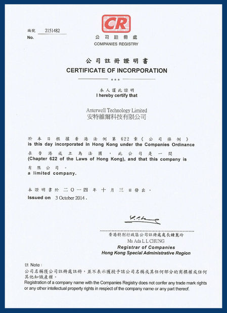
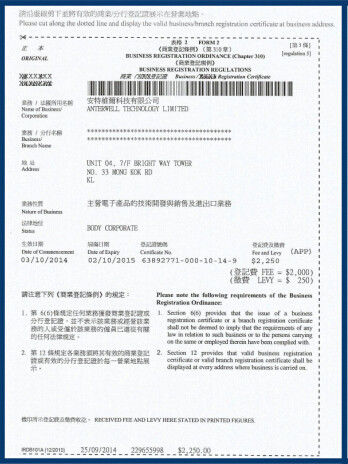
Anterwell Technology Ltd.
Anterwell Technology Ltd.
Large Original stock of IC Electronics Components, Transistors, Diodes etc.
High Quality, Reasonable Price, Fast Delivery.
Anterwell Technology Ltd.
Large Original stock of IC Electronics Components, Transistors, Diodes etc.
High Quality, Reasonable Price, Fast Delivery.
Product Details:
Payment & Shipping Terms:
|
| Average Rectified Forward Current: | 8 A (Per Leg) | Peak Rectified Forward Current: | 16 A ( Per Diode Leg) |
|---|---|---|---|
| Nonrepetitive Peak Surge Current: | 100 A | Operating Junction Temperature: | -65 To +175 °C |
| Storage Temperature: | -65 To +175 °C | Lead Temperature: | 260°C Max. For 10 Seconds |
| High Light: | npn smd transistor,silicon power transistors |
||
MUR1610CT, MUR1615CT, MUR1620CT, MUR1640CT, MUR1660CT
SWITCHMODETM Power Rectifiers
These state−of−the−art devices are a series designed for use in switching power supplies, inverters and as free wheeling diodes.
Features
• Ultrafast 35 and 60 Nanosecond Recovery Times
• 175°C Operating Junction Temperature
• Popular TO−220 Package
• Epoxy Meets UL 94 V−0 @ 0.125 in
• High Temperature Glass Passivated Junction
• High Voltage Capability to 600 V
• Low Leakage Specified @ 150°C Case Temperature
• Current Derating @ Both Case and Ambient Temperatures
• Pb−Free Packages are Available*
Mechanical Characteristics:
• Case: Epoxy, Molded
• Weight: 1.9 Grams (Approximately)
• Finish: All External Surfaces Corrosion Resistant and Terminal Leads are Readily Solderable
• Lead Temperature for Soldering Purposes: 260°C Max. for 10 Seconds
MAXIMUM RATINGS
| Rating | Symbol | MUR16 | Unit | ||||
| 10CT | 15CT | 20CT | 40CT | 60CT | |||
|
Peak Repetitive Reverse Voltage Working Peak Reverse Voltage DC Blocking Voltage |
VRRM VRWM VR |
100 | 150 | 200 | 400 | 600 | V |
|
Average Rectified Forward Current Per Leg Total Device, (Rated VR), TC = 150°C Total Device |
IF(AV) |
8.0 16 |
A | ||||
|
Peak Rectified Forward Current Per Diode Leg (Rated VR, Square Wave, 20 kHz), TC = 150°C |
IFM | 16 | A | ||||
|
Nonrepetitive Peak Surge Current (Surge applied at rated load conditions halfwave, single phase, 60 Hz) |
IFSM | 100 | A | ||||
| Operating Junction Temperature and Storage Temperature |
TJ, Tstg |
-65 to +175 | °C | ||||
Maximum ratings are those values beyond which device damage can occur. Maximum ratings applied to the device are individual stress limit values (not normal operating conditions) and are not valid simultaneously. If these limits are exceeded, device functional operation is not implied, damage may occur and reliability may be affected.
ULTRAFAST RECTIFIERS 8.0 AMPERES, 100−600 VOLTS
![]()
TO−220AB CASE 221A PLASTIC
MARKING DIAGRAM
![]()
A = Assembly Location
Y = Year
WW = Work Week
U16xx = Device Code
xx = 10, 15, 20, 40 or 60
G = Pb−Free Package
KA = Diode Polarity
High Power Rectifier Diode 1N4756A , Silicon Planar Zener Diodes
Bridge Type Rectifier Diode 1N4007 50 to 1000 Volts 1.0 Ampere
1N4742A Silicon Planar Zener Diodes for Stabilized Power Supply
Power Programmable IC Chips XC6SLX100-3FGG484C Spartan-6 Family Overview
128K Bytes Sound IC Chip Programming ATMEGA128-16AU 8 Bit Microcontroller
EMC Programmable IC Chips Compliant Slew Rate Limited EI , Timer IC Chip
SMD Power Mosfet Module L7812CV TO-220 Power Trans Electronic Compoents
2SD1594 3 Pin Transistor NEC NPN Power Transistor Switching High Speed
2N5459 Power Mosfet Transistor N-Channel To-92 Original Stock FSC