Anterwell Technology Ltd.
Anterwell Technology Ltd.
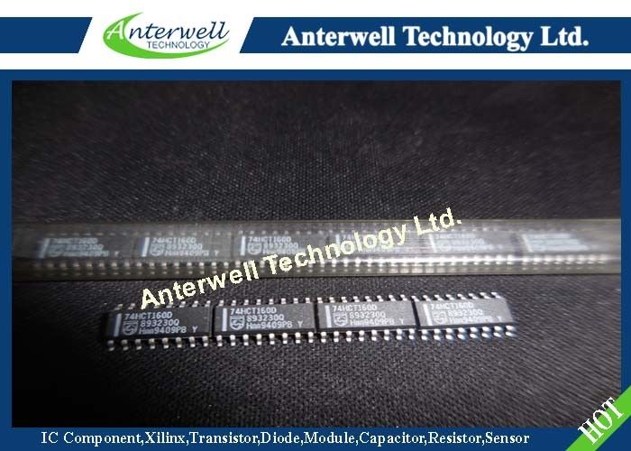
Large Original stock of IC Electronics Components, Transistors, Diodes etc.
High Quality, Reasonable Price, Fast Delivery.
Anterwell Technology Ltd.
Large Original stock of IC Electronics Components, Transistors, Diodes etc.
High Quality, Reasonable Price, Fast Delivery.
Product Details:
Payment & Shipping Terms:
|
| Feature 1: | Synchronous Counting And Loading | Feature 2: | Two Count Enable Inputs For N-bit Cascading |
|---|---|---|---|
| Feature 3: | Positive-edge Triggered Clock | Feature 4: | Asynchronous Reset |
| Output Capability: | Standard | Icc Category: | MSI |
| High Light: | electronics ic chip,integrated circuit ic |
||
FEATURES
• Synchronous counting and loading
• Two count enable inputs for n-bit cascading
• Positive-edge triggered clock
• Asynchronous reset
• Output capability: standard
• ICC category: MSI
GENERAL DESCRIPTION
The 74HC/HCT160 are high-speed Si-gate CMOS devices and are pin compatible with low power Schottky TTL (LSTTL). They are specified in compliance with JEDEC standard no. 7A.
The 74HC/HCT160 are synchronous presettable decade counters which feature an internal look-ahead carry and can be used for high-speed counting. Synchronous operation is provided by having all flip-flops clocked simultaneously on the positive-going edge of the clock (CP).
The outputs (Q0 to Q3) of the counters may be preset to a HIGH or LOW level. A LOW level at the parallel enable input (PE) disables the counting action and causes the data at the data inputs (D0 to D3) to be loaded into the counter on the positive-going edge of the clock (providing that the set-up and hold time requirements for PE are met). Preset takes place regardless of the levels at count enable inputs (CEP and CET).
A LOW level at the master reset input (MR) sets all four outputs of the flip-flops (Q0 to Q3) to LOW level regardless of the levels at CP, PE, CET and CEP inputs (thus providing an asynchronous clear function).
The look-ahead carry simplifies serial cascading of the counters. Both count enable inputs (CEP and CET) must be HIGH to count. The CET input is fed forward to enable the terminal count output (TC). The TC output thus enabled will produce a HIGH output pulse of a duration approximately equal to a HIGH level output of Q0. This pulse can be used to enable the next cascaded stage.
The maximum clock frequency for the cascaded counters is determined by the CP to TC propagation delay and CEP to CP set-up time, according to the following formula:
fmax = 1/t P (max) ( CP to TC) + tSU (CEP to CP)
PIN DESCRIPTION
| PIN NO. | SYMBOL | NAME AND FUNCTION |
|
1 2 3, 4, 5, 6 7 8 9 10 14, 13, 12, 11 15 16 |
MR CP D0 to D3 CEP GND PE CET Q0 to Q3 TC VCC |
asynchronous master reset (active LOW) clock input (LOW-to-HIGH, edge-triggered) data inputs count enable input ground (0 V) parallel enable input (active LOW) count enable carry input flip-flop outputs terminal count output positive supply voltage |
![]()
![]()
High Power Rectifier Diode 1N4756A , Silicon Planar Zener Diodes
Bridge Type Rectifier Diode 1N4007 50 to 1000 Volts 1.0 Ampere
1N4742A Silicon Planar Zener Diodes for Stabilized Power Supply
Power Programmable IC Chips XC6SLX100-3FGG484C Spartan-6 Family Overview
128K Bytes Sound IC Chip Programming ATMEGA128-16AU 8 Bit Microcontroller
EMC Programmable IC Chips Compliant Slew Rate Limited EI , Timer IC Chip
SMD Power Mosfet Module L7812CV TO-220 Power Trans Electronic Compoents
2SD1594 3 Pin Transistor NEC NPN Power Transistor Switching High Speed
2N5459 Power Mosfet Transistor N-Channel To-92 Original Stock FSC