Anterwell Technology Ltd.
Anterwell Technology Ltd.
Large Original stock of IC Electronics Components, Transistors, Diodes etc.
High Quality, Reasonable Price, Fast Delivery.
Anterwell Technology Ltd.
Large Original stock of IC Electronics Components, Transistors, Diodes etc.
High Quality, Reasonable Price, Fast Delivery.
Product Details:
Payment & Shipping Terms:
|
| Ambient Temperature Under Bias: | -40° To +125°C | Storage Temperature: | -65°C To +150°C |
|---|---|---|---|
| Voltage On VDD With Respect To VSS: | -0.3V To +6.5V | Total Power Dissipation: | 800 MW |
| Maximum Current Out Of VSS Pin: | 95 MA | Maximum Current Into VDD Pin: | 95 MA |
| Highlight: | electronic integrated circuit,linear integrated circuits |
||
Stock Offer (Hot Sell)
| Part No. | Quantity | Brand | D/C | Package |
| LM3488MM | 14816 | TI | 16+ | MSOP-8 |
| LM34DZ | 5112 | TI | 14+ | TO-92 |
| LM3526MX-L | 16692 | TI | 16+ | SOP-8 |
| LM358ADR | 71000 | TI | 15+ | SOP-8 |
| LM358AMX | 21853 | FSC | 16+ | SOP-8 |
| LM358APWR | 16686 | TI | 13+ | TSSOP-8 |
| LM358DR | 57000 | TI | 16+ | SOP-8 |
| LM358DR2G | 25000 | ON | 16+ | SOP-8 |
| LM358MX | 10438 | FSC | 08+ | SOP-8 |
| LM358S-13 | 73000 | DIODES | 11+ | SOP-8 |
| LM35DMX | 7069 | NS | 13+ | SOP-8 |
| LM35DZ | 8018 | TI | 16+ | TO-92 |
| LM3671MFX-1.8 | 9322 | NS | 16+ | SOT23-5 |
| LM384N | 6765 | NS | 86+ | DIP |
| LM385D-2.5 | 16757 | ON | 15+ | SOP-8 |
| LM385M3X-2.5 | 10509 | TI | 15+ | SOT23-3 |
| LM386MX-1 | 8505 | NS | 16+ | SOP-8 |
| LM3886T/NOPB | 3500 | TI | 15+ | ZIP-11 |
| LM3886TF | 2569 | NS | 14+ | ZIP-11 |
| LM393MX | 21332 | NSC | 13+ | SOP-8 |
| LM4040A25IDBZR | 61000 | TI | 15+ | SOT23-3 |
| LM4040AIM3-3.0 | 8166 | MAXIM | 16+ | SOT-23 |
| LM4040BIM3-3.0 | 21924 | TI | 13+ | SOT23-3 |
| LM4040C20IDBZR | 4600 | TI | 15+ | SOT23-5 |
| LM4040DIM3X-2.5 | 16828 | TI | 16+ | SOT23-3 |
| LM4040DYM3-2.5 | 21995 | MICREL | 15+ | SOT23-3 |
| LM4050BIM3X-2.5 | 9293 | TI | 13+ | SOT23-3 |
| LM431ACM3X | 12971 | NS | 16+ | SOT-23 |
| LM4670SD | 9264 | NS | 06+ | QFN |
| LM4853MM | 12686 | TI | 14+ | MSOP |
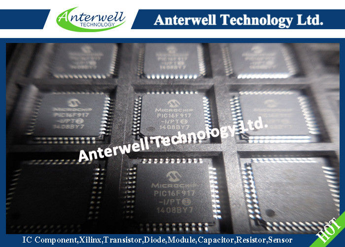
PIC16F913/914/916/917/946
28/40/44/64-Pin Flash-Based,
8-Bit CMOS Microcontrollers with LCD Driver and nanoWatt Technology
High-Performance RISC CPU:
• Only 35 instructions to learn:
- All single-cycle instructions except branches
• Operating speed:
- DC – 20 MHz oscillator/clock input
- DC – 200 ns instruction cycle
• Program Memory Read (PMR) capability
• Interrupt capability
• 8-level deep hardware stack
• Direct, Indirect and Relative Addressing modes
Special Microcontroller Features:
• Precision Internal Oscillator:
- Factory calibrated to ±1%, typical
- Software selectable frequency range of 8 MHz to 125 kHz
- Software tunable
- Two-Speed Start-up mode
- External Oscillator fail detect for critical applications
- Clock mode switching during operation for power savings
• Software selectable 31 kHz internal oscillator
• Power-Saving Sleep mode
• Wide operating voltage range (2.0V-5.5V)
• Industrial and Extended temperature range
• Power-on Reset (POR)
• Power-up Timer (PWRT) and Oscillator Start-up Timer (OST)
• Brown-out Reset (BOR) with software control option
• Enhanced Low-Current Watchdog Timer (WDT) with on-chip oscillator (software selectable nominal 268 seconds with full prescaler) with software enable
• Multiplexed Master Clear with pull-up/input pin
• Programmable code protection
• High-Endurance Flash/EEPROM cell:
- 100,000 write Flash endurance
- 1,000,000 write EEPROM endurance
- Flash/Data EEPROM retention: > 40 years
Low-Power Features:
• Standby Current:
- <100 nA @ 2.0V, typical
• Operating Current:
- 11 μA @ 32 kHz, 2.0V, typical
- 220 μA @ 4 MHz, 2.0V, typical
• Watchdog Timer Current:
- 1 μA @ 2.0V, typical
Peripheral Features:
• Liquid Crystal Display module:
- Up to 60/96/168 pixel drive capability on 28/40/64-pin devices, respectively
- Four commons
• Up to 24/35/53 I/O pins and 1 input-only pin:
- High-current source/sink for direct LED drive
- Interrupt-on-change pin
- Individually programmable weak pull-ups
• In-Circuit Serial Programming™ (ICSP™) via two pins
• Analog comparator module with:
- Two analog comparators
- Programmable on-chip voltage reference (CVREF) module (% of VDD)
- Comparator inputs and outputs externally accessible
• A/D Converter:
- 10-bit resolution and up to 8 channels
• Timer0: 8-bit timer/counter with 8-bit programmable prescaler
• Enhanced Timer1:
- 16-bit timer/counter with prescaler
- External Timer1 Gate (count enable)
- Option to use OSC1 and OSC2 as Timer1 oscillator if INTOSCIO or LP mode is selected
• Timer2: 8-bit timer/counter with 8-bit period register, prescaler and postscaler
• Addressable Universal Synchronous Asynchronous Receiver Transmitter (AUSART)
• Up to 2 Capture, Compare, PWM modules:
- 16-bit Capture, max. resolution 12.5 ns
- 16-bit Compare, max. resolution 200 ns
- 10-bit PWM, max. frequency 20 kHz
• Synchronous Serial Port (SSP) with I2C™
Absolute Maximum Ratings(†)
Ambient temperature under bias.........................................................................-40° to +125°C
Storage temperature ...................................................................................... -65°C to +150°C
Voltage on VDD with respect to VSS ................................................................. -0.3V to +6.5V
Voltage on MCLR with respect to Vss ............................................................. -0.3V to +13.5V
Voltage on all other pins with respect to VSS ........................................... -0.3V to (VDD + 0.3V)
Total power dissipation(1) ...........................................................................................800 mW
Maximum current out of VSS pin ................................................................................... 95 mA
Maximum current into VDD pin ..................................................................................... 95 mA
Input clamp current, IIK (VI < 0 or VI > VDD)...................................................................±20 mA
Output clamp current, IOK (Vo < 0 or Vo >VDD)..............................................................±20 mA
Maximum output current sunk by any I/O pin................................................................... 25 mA
Maximum output current sourced by any I/O pin .............................................................. 25 mA
Maximum current sourced by all ports (combined) ........................................................... 90 mA
Maximum current sunk by all ports (combined) ................................................................ 90 mA
Note 1: Power dissipation is calculated as follows: PDIS = VDD x {IDD – ∑ IOH} + ∑ {(VDD – VOH) x IOH} + ∑(VOL x IOL).
2: PORTD and PORTE are not implemented in PIC16F913/916 devices.
† NOTICE: Stresses above those listed under “Absolute Maximum Ratings” may cause permanent damage to the device. This is a stress rating only and functional operation of the device at those or any other conditions above those indicated in the operation listings of this specification is not implied. Exposure to maximum rating conditions for extended periods may affect device reliability.
High Power Rectifier Diode 1N4756A , Silicon Planar Zener Diodes
Bridge Type Rectifier Diode 1N4007 50 to 1000 Volts 1.0 Ampere
1N4742A Silicon Planar Zener Diodes for Stabilized Power Supply
Power Programmable IC Chips XC6SLX100-3FGG484C Spartan-6 Family Overview
128K Bytes Sound IC Chip Programming ATMEGA128-16AU 8 Bit Microcontroller
EMC Programmable IC Chips Compliant Slew Rate Limited EI , Timer IC Chip
SMD Power Mosfet Module L7812CV TO-220 Power Trans Electronic Compoents
2SD1594 3 Pin Transistor NEC NPN Power Transistor Switching High Speed
2N5459 Power Mosfet Transistor N-Channel To-92 Original Stock FSC